Active models via circulax#
Electronic-Photonic models can be simulated in a varienty of method using gdsfactory. In this notebook, active models will be demonstrated via Circulax. Circulax is a diffentiable simulator based on JAX enabling DC, AC, Transient and Harmonic balance support
# !uv add gdsfactory sax circulax # uncomment to install
import matplotlib.pyplot as plt
import numpy as np
import sax
from gdsfactory.gpdk import PDK

PDK.activate()

wl_broad = np.linspace(1.29, 1.33, 1000)
wl_narrow = np.linspace(1.54, 1.56, 1000)
cross_section = "strip"
import jax.numpy as jnp


def mmi1x2(wl=1.3) -> sax.SDict:
    """Assumes a perfect 1x2 splitter."""
    wl = jnp.atleast_1d(wl)
    t = 0.7  # algorithm fails at 0.5**0.5 for some reason
    return sax.reciprocal(
        {
            ("o1", "o2"): jnp.array(t, dtype=jnp.float64),
            ("o1", "o3"): jnp.array(t, dtype=jnp.complex128),
            ("o2", "o1"): jnp.array(t, dtype=jnp.float64),
            ("o3", "o1"): jnp.array(t, dtype=jnp.complex128),
        }
    )


def mmi2x2(wl=1.3) -> sax.SDict:
    wl = jnp.atleast_1d(wl)
    return sax.reciprocal(
        {
            ("o1", "o3"): 0.5**0.5,
            ("o1", "o4"): 1j * 0.5**0.5,
            ("o2", "o3"): 1j * 0.5**0.5,
            ("o2", "o4"): 0.5**0.5,
        }
    )


def straight(wl=1.3, length=10.0, neff=2.4) -> sax.SDict:
    return sax.reciprocal(
        {
            ("o1", "o2"): jnp.exp(2j * jnp.pi * neff * length / wl),
        }
    )


def grating(
    center_wavelength_um: float = 1.31,
    peak_loss_dB: float = 0.0,
    bandwidth_1dB: float = 0.02,
    wl: float = 1.31,
) -> sax.SDict:
    # Calculate transmission loss
    delta = wl - center_wavelength_um
    excess_loss = (delta / (0.5 * bandwidth_1dB)) ** 2
    loss_dB = peak_loss_dB + excess_loss

    # Convert dB to linear transmission coefficient
    T = 10.0 ** (-loss_dB / 20.0)

    # Numerical stability clip (Optional in SAX, but kept to match your original logic)
    T = jnp.minimum(T, 0.9999)

    # Ensure the transmission is a complex type, as S-parameters require it
    T_c = T.astype(jnp.complex128)
    zero = 1e-12 * jnp.ones_like(T_c)

    # Return the sdict mapping (out_port, in_port) -> S-parameter
    sdict = sax.sdict(
        {
            ("o1", "o2"): T_c,
            ("o2", "o1"): T_c,
            ("o1", "o1"): zero,
            ("o2", "o2"): zero,
        }
    )

    return sdict
import time

import jax

from circulax import compile_circuit
from circulax.components.electronic import Resistor
from circulax.components.photonic import OpticalSource

net_dict = {
    "instances": {
        "GND": {"component": "ground"},
        "Laser": {"component": "source", "settings": {"power": 1.0, "phase": 0.0}},
        # Input Coupling
        "GC_In": {
            "component": "grating",
            "settings": {},
        },
        "WG_In": {"component": "waveguide", "settings": {"length": 50.0}},
        # The Interferometer
        "Splitter": {"component": "splitter", "settings": {}},
        "WG_Long": {
            "component": "waveguide",
            "settings": {"length": 150.0},
        },  # Delta L = 100um
        "WG_Short": {"component": "waveguide", "settings": {"length": 100.0}},
        "Combiner": {
            "component": "splitter",
            "settings": {},
        },  # Reciprocal Splitter
        # Output Coupling
        "WG_Out": {"component": "waveguide", "settings": {"length": 50.0}},
        "GC_Out": {
            "component": "grating",
            "settings": {},
        },
        "Detector": {"component": "resistor", "settings": {"R": 1.0}},
    },
    "connections": {
        "GND,p1": ("Laser,p2", "Detector,p2"),
        # Input: Laser -> GC -> WG -> Splitter
        "Laser,p1": "GC_In,o1",
        "GC_In,o2": "WG_In,o1",
        "WG_In,o2": "Splitter,o1",
        # Arms
        "Splitter,o2": "WG_Long,o1",
        "Splitter,o3": "WG_Short,o1",
        "WG_Long,o2": "Combiner,o2",
        "WG_Short,o2": "Combiner,o3",
        # Output: Combiner -> WG -> GC -> Detector
        "Combiner,o1": "WG_Out,o1",
        "WG_Out,o2": "GC_Out,o2",
        "GC_Out,o1": "Detector,p1",
    },
}

models_map = {
    # "grating": circulax_models['FGCOTE_FC10_WG_380'],
    "grating": grating,
    "waveguide": straight,
    "splitter": mmi1x2,
    "source": OpticalSource,
    "resistor": Resistor,
    "ground": lambda: 0,
}
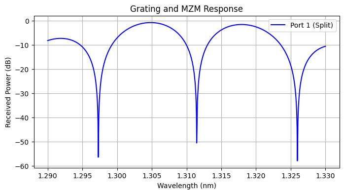
print("--- DEMO: Photonic Splitter & Grating Link (Wavelength Sweep) ---")

circuit = compile_circuit(net_dict, models_map, is_complex=True)

wavelengths = jnp.linspace(1260, 1360, 250)

print("Sweeping Wavelength...")
dc_sweep_callable = jax.jit(circuit)
start = time.time()
solutions = dc_sweep_callable(wl=wl_broad)
total = time.time() - start
print(f"Sweep time: {total:.3f}s")

v_out1 = circuit.get_port_field(solutions, "Detector,p1")
p_out1_db = 10.0 * jnp.log10(jnp.abs(v_out1) ** 2 + 1e-12)

plt.figure(figsize=(8, 4))
plt.plot(wl_broad, p_out1_db, "b-", label="Port 1 (Split)")
plt.title("Grating and MZM Response")
plt.xlabel("Wavelength (nm)")
plt.ylabel("Received Power (dB)")
plt.legend()
plt.grid(True)
plt.show()
--- DEMO: Photonic Splitter & Grating Link (Wavelength Sweep) ---
Sweeping Wavelength...
Sweep time: 2.848s
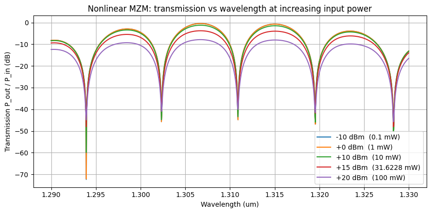
Non-linear waveguide model#
Silicon waveguides acquire intensity-dependent loss at high powers (two-photon absorption, free-carrier absorption). Below we register a nonlinear circulax component that augments the linear propagation with a closed-form power-dependent loss term, swap it into the MZM netlist from the previous section, and sweep the Mach-Zehnder response over wavelength and input laser power to show the compression that appears once the intra-waveguide power becomes comparable to the nonlinear scale.
from circulax.components.base_component import component
from circulax.s_transforms import s_to_y


@component(ports=("o1", "o2"))
def OpticalWaveguideNonlinear(
    signals,
    s,
    length_um: float = 100.0,
    loss_dB_cm: float = 1.0,
    neff: float = 2.4,
    n_group: float = 4.0,
    wl0: float = 1.31,
    wl: float = 1.31,
    nll_coefficient: float = 0.0,
):
    """Waveguide with linear dispersion + loss and intensity-dependent loss.

    Units:
        ``length_um``        micrometres
        ``wl``, ``wl0``      micrometres
        ``power`` (in sim)   milliwatts (so ``|field|^2`` is in mW)
        ``nll_coefficient``  1/(mW^2 * mm) — with this convention a value
                             around ``5e-3`` is a strong nonlinearity.

    The linear transmission follows a first-order dispersion expansion around
    ``wl0``. A power-dependent amplitude attenuation ``1 / sqrt(1 + 2 gamma L P^2)``
    is applied on top; it is the NaN-free algebraic rewrite of the sax
    ``waveguide_nonlinear`` formula ``1/sqrt(P^-2 + 2 gamma L)/P``. Ports
    ``o1``/``o2`` match the SAX waveguide convention so it drops into the
    MZM netlist above.
    """
    d_lam = wl - wl0
    slope = (neff - n_group) / wl0
    n_eff_disp = neff + slope * d_lam

    phi = 2.0 * jnp.pi * n_eff_disp * (length_um / wl)
    loss_val = loss_dB_cm * (length_um / 1e4)
    T_mag = 10.0 ** (-loss_val / 20.0)
    T_linear = T_mag * jnp.exp(-1j * phi)

    # Use real^2 + imag^2 instead of abs(...)**2 to avoid the singular sqrt
    # derivative at zero. P is in mW since source amplitudes are sqrt(mW).
    p_in = signals.o1.real**2 + signals.o1.imag**2
    p_out = signals.o2.real**2 + signals.o2.imag**2
    p_linear = p_in + p_out
    length_mm = length_um * 1e-3
    a = 2.0 * nll_coefficient * length_mm
    nl_loss_power = 1.0 / jnp.sqrt(1.0 + a * p_linear**2)
    T = jnp.sqrt(nl_loss_power) * T_linear

    S = jnp.array([[0.0, T], [T, 0.0]], dtype=jnp.complex128)
    Y = s_to_y(S)
    v_vec = jnp.array([signals.o1, signals.o2], dtype=jnp.complex128)
    i_vec = Y @ v_vec
    return {"o1": i_vec[0], "o2": i_vec[1]}, {}
# Derive the nonlinear MZM from `net_dict` by swapping every "waveguide"
# instance for its nonlinear counterpart (renaming `length` -> `length_um`
# along the way). Connections are reused verbatim.
# `nll_coefficient` is in 1/(mW^2 * mm); 5e-3 is a strong value.
NLL = 5e-3


def _linear_to_nl(inst):
    """Rebuild a `waveguide` instance as a `waveguide_nl` with the same length."""
    if inst["component"] != "waveguide":
        return inst
    return {
        "component": "waveguide_nl",
        "settings": {"length_um": inst["settings"]["length"], "nll_coefficient": NLL},
    }


nl_net_dict = {
    "instances": {
        name: _linear_to_nl(inst) for name, inst in net_dict["instances"].items()
    },
    "connections": net_dict["connections"],
}

# Inherit the passive models map (minus the stale `ground` lambda that recent
# circulax rejects) and register the new nonlinear waveguide.
nl_models_map = {
    **{k: v for k, v in models_map.items() if k != "ground"},
    "waveguide_nl": OpticalWaveguideNonlinear,
}

nl_circuit = compile_circuit(nl_net_dict, nl_models_map, is_complex=True)
print("--- DEMO: Nonlinear MZM Response (Wavelength x Power Sweep) ---")

# Powers in mW (source convention): -10, 0, 10, 15, 20 dBm.
power_dBm = jnp.array([-10.0, 0.0, 10.0, 15.0, 20.0])
powers_mW = 10.0 ** (power_dBm / 10.0)


@jax.jit
def sweep_power(p):
    return nl_circuit(wl=wl_broad, power=p)


start = time.time()
solutions_2d = jax.vmap(sweep_power)(powers_mW)  # (n_power, n_wl, 2*sys_size)
solutions_2d.block_until_ready()
total = time.time() - start
print(f"2D sweep ({len(powers_mW)} powers x {len(wl_broad)} wavelengths): {total:.3f}s")

v_out_2d = nl_circuit.get_port_field(solutions_2d, "Detector,p1")
p_out_2d_mW = jnp.abs(v_out_2d) ** 2  # shape (n_power, n_wl) in mW

plt.figure(figsize=(9, 4.5))
for i, (p_mW, p_dBm) in enumerate(zip(powers_mW, power_dBm)):
    t_db = 10.0 * jnp.log10(p_out_2d_mW[i] / float(p_mW) + 1e-18)
    plt.plot(wl_broad, t_db, label=f"{float(p_dBm):+.0f} dBm  ({float(p_mW):g} mW)")
plt.title("Nonlinear MZM: transmission vs wavelength at increasing input power")
plt.xlabel("Wavelength (um)")
plt.ylabel("Transmission P_out / P_in (dB)")
plt.legend(loc="lower right")
plt.grid(True)
plt.tight_layout()
plt.show()
--- DEMO: Nonlinear MZM Response (Wavelength x Power Sweep) ---
2D sweep (5 powers x 1000 wavelengths): 4.892s
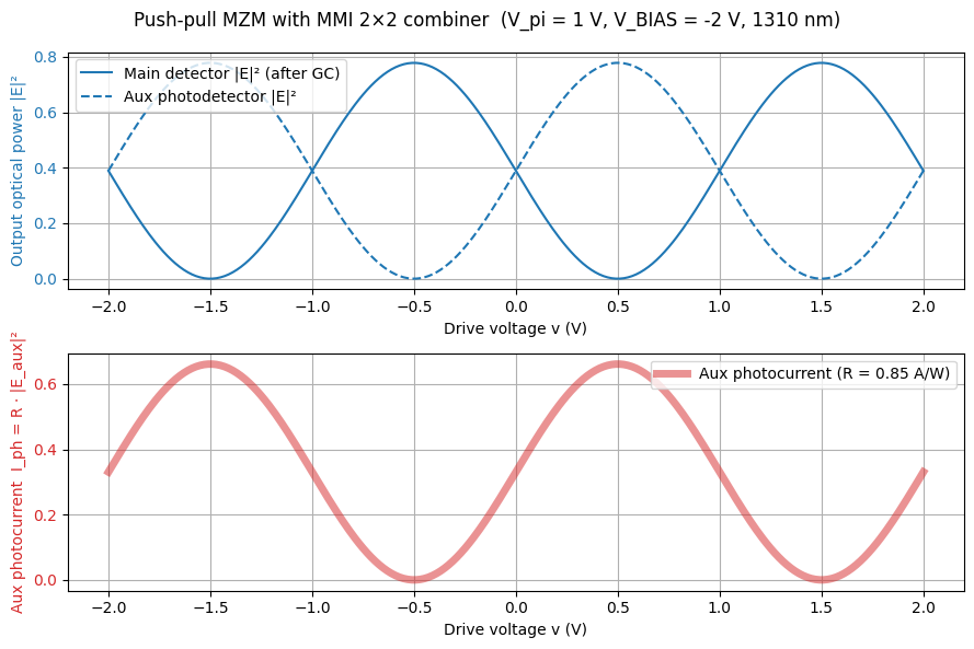
Push-pull MZM with MMI 2×2 combiner and auxiliary photodetector#
We build a balanced push-pull MZM driven from two phase-shifter arms and terminated in the PDK’s M22OTE_WG_380 (a true 2×2 MMI) as the combiner. That opens up the second MZM output — normally dark — as the natural place to hook up an auxiliary photodetector to read the complementary modulation, exactly the signal a balanced receiver subtracts against the main photodetector to cancel common-mode noise.
The phase shifter now has electrical anode / cathode ports instead of a scalar voltage_V setting, mirroring the interface of the PDK’s PN-junction phase shifter (to be integrated later). The applied bias is V_bias = V_anode − V_cathode, and the model is only physically meaningful in reverse bias (V_bias < 0) where widening the depletion region shifts n_eff. We drive each arm with its own VoltageSource sitting at a DC reverse bias V_BIAS = −2 V with a push-pull swing ±v/2 on top, so V_bias ∈ [−3, −1] V stays negative across the full [−2Vπ, +2Vπ] drive sweep. With vpiL = 1 V·cm and arm length 1 cm we get Vπ = 1 V, and the differential phase is Δφ = (π / Vπ) · v (common-mode bias cancels through the MZM).
Below we:
Register an inlined copy of
SimplePhaseShifterwith(o1, o2, anode, cathode)ports (currently on the circulaxphase-shifterbranch) and a minimal 3-portSimplePhotodetector.Build the MZM netlist with the PDK MMI2x2 as the combiner, two
VoltageSourceinstances driving the phase-shifter anodes, both cathodes tied to ground, and the aux output going straight into the new photodetector (with a 1 Ω cathode load so we can read the photocurrent back out).Sweep the push-pull drive and plot the main/aux optical powers and the aux photocurrent.
Dependency note:
SimplePhaseShiftercurrently lives on the circulaxphase-shifterbranch. The inlined definition below mirrors it so the notebook runs self-contained; once that branch is merged, replace the class withfrom circulax.components.photonic import SimplePhaseShifter.
from circulax.components.electronic import VoltageSource
from circulax.utils import update_params_dict


# --- Inlined SimplePhaseShifter (mirrors circulax phase-shifter branch) ---
def _optical_currents_from_phase_and_loss(
    neff_total, loss_dBcm, length_um, wavelength_nm, o1, o2
):
    phi = 2.0 * jnp.pi * neff_total * (length_um / wavelength_nm) * 1000.0
    loss_val = loss_dBcm * (length_um / 10000.0)
    T_mag = 10.0 ** (-loss_val / 20.0)
    T = T_mag * jnp.exp(-1j * phi)
    S = jnp.array([[0.0, T], [T, 0.0]], dtype=jnp.complex128)
    Y = s_to_y(S)
    v_opt = jnp.array([o1, o2], dtype=jnp.complex128)
    return Y @ v_opt


@component(ports=("o1", "o2", "anode", "cathode"))
def SimplePhaseShifter(
    signals,
    s,
    vpiL: float = 1.0,
    loss_dBcm: float = 0.0,
    length_um: float = 100.0,
    neff0: float = 2.4,
    wavelength_nm: float = 1310.0,
):
    """Scalar-VpiL phase shifter driven through PN-junction-style electrical ports.

    The applied bias is ``V_bias = V_anode - V_cathode``, and the phase
    shift scales linearly with it: ``dn_eff(V_bias) = (lambda / (2 * VpiL_cm)) * V_bias``.
    Physically this is a depletion-mode PN-junction modulator, so the model
    is **only meaningful in reverse bias** (``V_bias < 0``); driving it
    forward isn't a hardware-realistic operating point (the sign of the
    effective index change is absorbed into the sign of ``vpiL``).

    The electrical ports draw no current in this ideal model — the junction
    is treated as infinite-impedance — so whatever external network the
    caller attaches (voltage source, bias tee, etc.) sets ``V_anode`` and
    ``V_cathode`` directly. Both terminals must be pinned externally (to
    sources, grounds, or resistive loads) to avoid a floating node. When
    the PDK's ``pn_junction_phase_shifter`` is available, swap this class
    for that one — it adds a real depletion capacitance and optionally a
    small-signal conductance, but the port interface is identical.
    """
    v_bias = jnp.real(signals.anode - signals.cathode)
    dn_dV = (wavelength_nm * 1e-9) / (2.0 * (vpiL / 1e2))
    dneff = dn_dV * v_bias
    i_opt = _optical_currents_from_phase_and_loss(
        neff0 + dneff,
        jnp.asarray(loss_dBcm),
        length_um,
        wavelength_nm,
        signals.o1,
        signals.o2,
    )
    # Electrical ports: no current flows (infinite junction impedance).
    return {"o1": i_opt[0], "o2": i_opt[1], "anode": 0.0, "cathode": 0.0}, {}


# --- 3-port photodetector: matched optical input + anode/cathode -----------
@component(ports=("o1", "anode", "cathode"))
def SimplePhotodetector(signals, s, responsivity: float = 0.85):
    """Photodiode: matched optical input + anode/cathode electrical terminals.

    Optical port ``o1``: **matched 1-port termination**. Built explicitly from
    ``S = [[0]]`` (reflection coefficient Γ = 0) via ``s_to_y``, giving
    ``Y = 1/z0 = 1`` with circulax's ``z0 = 1``. The MNA port current returned
    for ``o1`` is ``Y · V_o1 = V_o1`` — the current *drawn into* the component
    (what a matched load absorbs). This is **not** a reflected field: the
    opposite extremes would be an open circuit (returning ``0``; Γ = +1,
    100% in-phase reflection) or a short (Γ = −1). Absorbed optical power is
    ``|V_o1|²``.

    Electrical ports ``anode`` / ``cathode``: the absorbed power drives an
    internal photocurrent ``I_ph = responsivity · |V_o1|²`` that flows out of
    the cathode into the external circuit and returns through the anode —
    reverse-bias / photoconductive convention. Sensing ``V_cathode`` across a
    load resistor to ground therefore reads ``I_ph · R_load``.
    """
    S_abs = jnp.array([[0.0 + 0.0j]], dtype=jnp.complex128)
    Y_abs = s_to_y(S_abs)
    i_o1 = (Y_abs @ jnp.array([signals.o1], dtype=jnp.complex128))[0]
    p_abs = signals.o1.real**2 + signals.o1.imag**2
    i_ph = responsivity * p_abs
    return {"o1": i_o1, "anode": i_ph, "cathode": -i_ph}, {}


# --- Device parameters -----------------------------------------------------
L_arm_um = 1.0e4  # arm length in um (1 cm)
VPI_L = 1.0  # V*cm
LAMBDA_NM = 1310.0
V_pi = VPI_L / (L_arm_um * 1e-4)  # 1 V for L = 1 cm
R_LOAD = 1.0  # ohms — with R=1, V_cathode numerically equals I_ph
RESPONSIVITY = 0.85  # A/W
V_BIAS = -2.0  # DC reverse bias applied on each arm's anode (cathodes at GND)
PS_GROUP = "phase_shifter"
VSRC_GROUP = "voltage_source"

# --- Netlist: derived from net_dict by replacing the passive arms + MMI1x2 -
# combiner with active phase-shifter arms, electrical drive, and a 2x2 MMI
# feeding a main detector + auxiliary photodetector with sense load.
_ps_settings = {
    "vpiL": VPI_L,
    "length_um": L_arm_um,
    "loss_dBcm": 1.0,
    "wavelength_nm": LAMBDA_NM,
}

bal_net_dict = {
    "instances": {
        # Reuse the passive optical infra from `net_dict` (Laser, GC_In,
        # WG_In, Splitter, WG_Out, GC_Out, Detector, GND); drop the arms and
        # MMI1x2 combiner that are being replaced.
        **{
            k: v
            for k, v in net_dict["instances"].items()
            if k not in ("WG_Long", "WG_Short", "Combiner")
        },
        # New pieces: MMI2x2 combiner, active arms with electrical drive,
        # auxiliary photodetector + load on the complementary output.
        "Combiner": {"component": "mmi2x2", "settings": {}},
        "PS_Top": {"component": "phase_shifter", "settings": _ps_settings},
        "PS_Bot": {"component": "phase_shifter", "settings": _ps_settings},
        "V_Top": {"component": "voltage_source", "settings": {"V": V_BIAS}},
        "V_Bot": {"component": "voltage_source", "settings": {"V": V_BIAS}},
        "AuxDetector": {
            "component": "photodetector",
            "settings": {"responsivity": RESPONSIVITY},
        },
        "AuxLoad": {"component": "resistor", "settings": {"R": R_LOAD}},
    },
    "connections": {
        # Reuse the input chain (Laser -> GC_In -> WG_In -> Splitter) and
        # main output chain (WG_Out -> GC_Out -> Detector); drop the old
        # arm/combiner entries since those ports no longer exist.
        **{
            k: v
            for k, v in net_dict["connections"].items()
            if k not in ("WG_Long,o2", "WG_Short,o2", "Combiner,o1")
        },
        # Extend the ground net with new electrical returns + cathodes.
        "GND,p1": net_dict["connections"]["GND,p1"]
        + (
            "AuxDetector,anode",
            "AuxLoad,p2",
            "V_Top,p2",
            "V_Bot,p2",
            "PS_Top,cathode",
            "PS_Bot,cathode",
        ),
        # Splitter outputs -> phase-shifter inputs.
        "Splitter,o2": "PS_Top,o1",
        "Splitter,o3": "PS_Bot,o1",
        # Electrical drive: each V-source sets its arm's anode.
        "V_Top,p1": "PS_Top,anode",
        "V_Bot,p1": "PS_Bot,anode",
        # Arms -> MMI2x2 combiner (o1/o2 inputs, o3/o4 outputs).
        "PS_Top,o2": "Combiner,o1",
        "PS_Bot,o2": "Combiner,o2",
        "Combiner,o3": "WG_Out,o1",  # main ("through") output
        "Combiner,o4": "AuxDetector,o1",  # auxiliary ("bar") output
        "AuxDetector,cathode": "AuxLoad,p1",  # photocurrent into load
    },
}

# Inherit the passive models map and extend with the electrical + active pieces.
bal_models_map = {
    **{k: v for k, v in models_map.items() if k != "ground"},
    "mmi2x2": mmi2x2,
    "voltage_source": VoltageSource,
    "phase_shifter": SimplePhaseShifter,
    "photodetector": SimplePhotodetector,
}

bal_circuit = compile_circuit(bal_net_dict, bal_models_map, is_complex=True)
print(f"Balanced MZM compiled.  V_pi = {V_pi:g} V,  V_BIAS = {V_BIAS:+g} V")
print("  groups:", list(bal_circuit.groups.keys()))
Balanced MZM compiled.  V_pi = 1 V,  V_BIAS = -2 V
  groups: ['source', 'grating', 'waveguide', 'splitter', 'resistor', 'mmi2x2', 'phase_shifter', 'voltage_source', 'photodetector']
# Push-pull sweep with the balanced-output MZM. Each arm is driven by its
# own VoltageSource; pushing V_Top to V_BIAS + v/2 and V_Bot to V_BIAS - v/2
# keeps both junctions reverse-biased while stepping the differential drive v.
v_drive_bal = jnp.linspace(-2.0 * V_pi, 2.0 * V_pi, 401)


def solve_bal_push_pull(v):
    g = update_params_dict(
        bal_circuit.groups, VSRC_GROUP, "V_Top", "V", V_BIAS + v / 2.0
    )
    g = update_params_dict(g, VSRC_GROUP, "V_Bot", "V", V_BIAS - v / 2.0)
    return bal_circuit.with_groups(g)(wl=LAMBDA_NM * 1e-3)


start = time.time()
sol_bal = jax.jit(jax.vmap(solve_bal_push_pull))(v_drive_bal)
sol_bal.block_until_ready()
print(f"sweep time ({len(v_drive_bal)} voltages): {time.time() - start:.3f}s")

p_main = jnp.abs(bal_circuit.get_port_field(sol_bal, "Detector,p1")) ** 2
p_aux = jnp.abs(bal_circuit.get_port_field(sol_bal, "AuxDetector,o1")) ** 2
v_cathode = bal_circuit.get_port_field(sol_bal, "AuxDetector,cathode")
i_photo = v_cathode.real / R_LOAD

C_POWER = "tab:blue"
C_CURRENT = "tab:red"

fig, axes = plt.subplots(nrows=2, figsize=(9, 6))
ax1, ax2 = axes

ax1.plot(v_drive_bal, p_main, color=C_POWER, label="Main detector |E|² (after GC)")
ax1.plot(
    v_drive_bal, p_aux, color=C_POWER, linestyle="--", label="Aux photodetector |E|²"
)
ax1.set_xlabel("Drive voltage v (V)")
ax1.set_ylabel("Output optical power |E|²", color=C_POWER)
ax1.tick_params(axis="y", labelcolor=C_POWER)
ax1.grid(True)
ax1.legend(loc="upper left")

ax2.plot(
    v_drive_bal,
    i_photo,
    color=C_CURRENT,
    label=f"Aux photocurrent (R = {RESPONSIVITY} A/W)",
    linewidth=5,
    alpha=0.5,
)
ax2.set_xlabel("Drive voltage v (V)")
ax2.set_ylabel("Aux photocurrent  I_ph = R · |E_aux|²", color=C_CURRENT)
ax2.tick_params(axis="y", labelcolor=C_CURRENT)
# Align the two axes so the optical power (mW) and photocurrent (mA)
# share the same zero when RESPONSIVITY = 1.
ax2.set_ylim(ax1.get_ylim()[0] * RESPONSIVITY, ax1.get_ylim()[1] * RESPONSIVITY)
ax2.grid()
ax2.legend(loc="upper right")

plt.suptitle(
    f"Push-pull MZM with MMI 2×2 combiner  (V_pi = {V_pi:g} V, V_BIAS = {V_BIAS:+g} V, {LAMBDA_NM:.0f} nm)"
)
plt.tight_layout()
plt.show()
sweep time (401 voltages): 5.375s
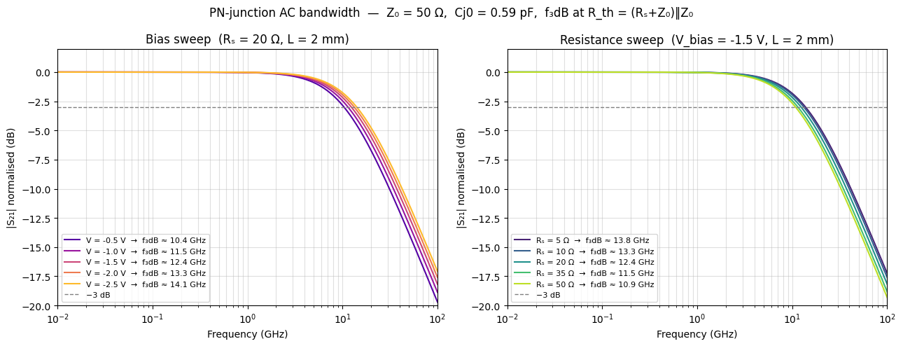
PN-junction phase shifter: DC transfer function and AC bandwidth#
The PN-junction phase shifter couples the depletion-mode plasma-dispersion effect to the optical field. Two lookup tables — VπL vs voltage and insertion loss vs voltage — are baked into a differentiable model by pn_junction_phase_shifter_factory. Its electrical model is a full Shockley diode plus an abrupt-junction depletion capacitance:
where \(C_{j0} = \rho_C \cdot L\) scales with arm length, and \(V_{bi}\), \(M\) are junction parameters. Series contact and metal resistance \(R_s = \rho_s \cdot L\) sets the RC time constant that limits modulation bandwidth:
Deeper reverse bias lowers \(C_j\) and improves bandwidth at the cost of weaker index change (higher \(V_\pi\)).
Below we:
Build a push-pull MZM with
PNJunctionPhaseShifterarms and an MMI 2×2 combiner and sweep the DC optical transfer function.Run an AC small-signal sweep with
setup_ac_sweepto map out \(|S_{21}|\) vs frequency — first sweeping reverse-bias voltage (showing the capacitance-limited roll-off shift), then sweeping series resistance (showing the \(R\)-\(C\) bandwidth tradeoff).
from jax.typing import ArrayLike

# ── Calibration tables (VπL vs V and loss vs V) ────────────────────────────────
_DEFAULT_VPIL_VS_VOLTAGE = jnp.array(
    [[1.4, 1.5, 1.6], [-0.5, -1.5, -2.5]]
)  # row 0: VπL (V·cm), row 1: voltage (V)

_DEFAULT_LOSS_VS_VOLTAGE = jnp.array(
    [[12.0, 11.5, 11.0], [-0.5, -1.5, -2.5]]
)  # row 0: loss (dB/cm), row 1: voltage (V)


def _build_phase_shifter_grids(
    vpiL_vs_voltage: ArrayLike,
    loss_vs_voltage: ArrayLike,
    center_wavelength_nm: float,
    vpil_fit_degree: int,
    il_fit_degree: int,
    grid_V: ArrayLike | None,
) -> tuple[jax.Array, jax.Array, jax.Array]:
    """Bake VπL and loss calibration tables into baked 1-D lookup grids.

    Shared by :func:`phase_shifter_factory` and
    :func:`pn_junction_phase_shifter_factory`. Integrates
    ``dn_eff/dV = λ / (2·VπL_cm)`` via trapezoid rule, polynomial-fits both the
    resulting ``Δn_eff(V)`` and the loss(V) curve, and resamples onto ``grid_V``.

    Returns:
        A three-tuple ``(grid_V, dneff_grid, loss_grid)`` of JAX arrays.

    """
    with jax.ensure_compile_time_eval():
        vpiL_arr = jnp.asarray(vpiL_vs_voltage)
        loss_arr = jnp.asarray(loss_vs_voltage)

        # Sort both calibrations by ascending voltage (polyfit and trapezoid
        # integration both require monotonic abscissae).
        order_vpil = jnp.argsort(vpiL_arr[1])
        v_vpil = vpiL_arr[1][order_vpil]
        vpil_sorted = vpiL_arr[0][order_vpil]
        order_loss = jnp.argsort(loss_arr[1])
        v_loss = loss_arr[1][order_loss]
        il_sorted = loss_arr[0][order_loss]

        # Default grid: combined data range with ±0.5 V margin to permit mild
        # extrapolation (e.g. querying V=0 when data stops at -0.5 V).
        v_span = jnp.concatenate([v_vpil, v_loss])
        v_min = float(jnp.min(v_span)) - 0.5
        v_max = float(jnp.max(v_span)) + 0.5
        out_grid = (
            jnp.asarray(grid_V)
            if grid_V is not None
            else jnp.linspace(v_min, v_max, 256)
        )

        # Integrate dn/dV = λ / (2·VπL_cm) → Δn_eff(V) at calibration voltages,
        # polyfit, and resample onto out_grid.
        wavelength_m = center_wavelength_nm * 1e-9
        unit_conversion = 1e2  # V·cm → V·m
        dn_dV = wavelength_m / (2.0 * (vpil_sorted / unit_conversion))
        dv = jnp.diff(v_vpil)
        areas = ((dn_dV[:-1] + dn_dV[1:]) / 2.0) * dv
        deltas = jnp.concatenate([jnp.array([0.0]), jnp.cumsum(areas)])
        dneff_coeffs = jnp.polyfit(v_vpil, deltas, deg=vpil_fit_degree)
        dneff_grid = jnp.polyval(dneff_coeffs, out_grid)

        loss_coeffs = jnp.polyfit(v_loss, il_sorted, deg=il_fit_degree)
        loss_grid = jnp.polyval(loss_coeffs, out_grid)

    return out_grid, dneff_grid, loss_grid


def _optical_currents_from_phase_and_loss(
    neff_total: jax.Array,
    loss_dBcm: jax.Array,
    length_um: float,
    wavelength_nm: float,
    o1: jax.Array,
    o2: jax.Array,
) -> jax.Array:
    """Build the 2×2 waveguide S-matrix from phase/loss and return ``Y @ [o1, o2]``.

    Shared between all phase-shifter factories (tabulated and scalar). Converts
    ``neff_total`` and ``loss_dBcm`` to a complex transmission ``T``, assembles
    ``S = [[0, T], [T, 0]]``, and returns the nodal optical currents.
    """
    phi = 2.0 * jnp.pi * neff_total * (length_um / wavelength_nm) * 1000.0
    loss_val = loss_dBcm * (length_um / 10000.0)
    T_mag = 10.0 ** (-loss_val / 20.0)

    T = T_mag * jnp.exp(-1j * phi)
    S = jnp.array([[0.0, T], [T, 0.0]], dtype=jnp.complex128)
    Y = s_to_y(S)

    v_opt = jnp.array([o1, o2], dtype=jnp.complex128)
    return Y @ v_opt


def _optical_port_currents(
    voltage_V: jax.Array,
    o1: jax.Array,
    o2: jax.Array,
    length_um: float,
    neff0: float,
    wavelength_nm: float,
    grid_V: jax.Array,
    dneff_grid: jax.Array,
    loss_grid: jax.Array,
) -> jax.Array:
    """Compute optical port currents ``(i_o1, i_o2)`` from baked calibration grids.

    Looks up ``Δn_eff(V)`` and ``loss_dBcm(V)`` via 1-D interpolation and delegates
    the S-matrix assembly to :func:`_optical_currents_from_phase_and_loss`.
    """
    dneff = jnp.interp(voltage_V, grid_V, dneff_grid)
    loss_dBcm = jnp.interp(voltage_V, grid_V, loss_grid)
    return _optical_currents_from_phase_and_loss(
        neff0 + dneff, loss_dBcm, length_um, wavelength_nm, o1, o2
    )
import numpy as np
from circulax import setup_ac_sweep
def pn_junction_ps_factory(
*,
vpiL_vs_voltage=_DEFAULT_VPIL_VS_VOLTAGE,
loss_vs_voltage=_DEFAULT_LOSS_VS_VOLTAGE,
center_wavelength_um: float = 1.31,
vpil_fit_degree: int = 2,
il_fit_degree: int = 1,
grid_V=None,
):
"""PN-junction electro-optic phase shifter factory with SAX-style parameters.
Parameters ``wl`` (µm) and ``length`` (µm) follow the SAX waveguide convention.
"""
_grid_V, _dneff_grid, _loss_grid = _build_phase_shifter_grids(
vpiL_vs_voltage,
loss_vs_voltage,
center_wavelength_um * 1e3,
vpil_fit_degree,
il_fit_degree,
grid_V,
)
@component(ports=("anode", "cathode", "o1", "o2"))
def PNJunctionPhaseShifter(
signals,
s,
length: float = 100.0, # µm — SAX convention
neff0: float = 2.4,
wl: float = 1.31, # µm — SAX convention
n: float = 1.0,
Cj0_per_um_fF: float = 0.296,
Vbi: float = 1.79,
M: float = 0.49,
Is: float = 1e-12,
Vt: float = 25.85e-3,
):
voltage_V = jnp.real(signals.anode - signals.cathode)
i_opt = _optical_port_currents(
voltage_V,
signals.o1,
signals.o2,
length,
neff0,
wl * 1e3, # length in µm, wl*1e3 converts µm → nm
_grid_V,
_dneff_grid,
_loss_grid,
)
Cj0 = Cj0_per_um_fF * length * 1e-15
vj_clip = jnp.clip(voltage_V, -5.0, 5.0)
i_elec = Is * (jnp.exp(vj_clip / (n * Vt)) - 1.0)
vj_ratio = jnp.clip(voltage_V / Vbi, -10.0, 0.95)
q_j = -Cj0 * Vbi / (1.0 - M) * (jnp.power(1.0 - vj_ratio, 1.0 - M) - 1.0)
return (
{"anode": i_elec, "cathode": -i_elec, "o1": i_opt[0], "o2": i_opt[1]},
{"anode": q_j, "cathode": -q_j},
)
return PNJunctionPhaseShifter
# ── Device / process parameters ────────────────────────────────────────────────
WL_PN_UM = 1.31 # µm
L_PN = 2_000.0 # µm — 2 mm arm; gives f_3dB > 10 GHz with Rₛ = 20 Ω
CJ0_PER_UM_FF = 0.296 # fF/µm – zero-bias junction capacitance density
RHO_OHM_UM = 0.01 # Ω·µm – series resistivity per µm (contact + metal)
R_SERIES_PN = RHO_OHM_UM * L_PN # 20 Ω total series resistance per arm
V_BIAS_PN = -1.5 # DC reverse bias (V) – centre of calibration table
Z0_RF = 50.0 # reference impedance for RF S-parameter analysis
# ── Build the PN-junction phase-shifter component ──────────────────────────────
PNJunctionPS = pn_junction_ps_factory(center_wavelength_um=WL_PN_UM)
_pn_inst_settings = {
"length": L_PN,
"wl": WL_PN_UM,
"Cj0_per_um_fF": CJ0_PER_UM_FF,
}
# ── Models map ─────────────────────────────────────────────────────────────────
_pn_models_map = {
**{k: v for k, v in models_map.items() if k != "ground"},
"mmi2x2": mmi2x2,
"voltage_source": VoltageSource,
"pn_ps": PNJunctionPS,
"photodetector": SimplePhotodetector,
}
# ── Push-pull MZM netlist with PN-junction phase shifters ──────────────────────
# Each arm: VoltageSource → series resistor (RS_*) → PN-junction anode.
# Cathodes are grounded. The 2×2 MMI combiner routes the complementary
# output to an aux photodetector.
pn_net = {
"instances": {
"GND": {"component": "ground"},
"Laser": {"component": "source", "settings": {"power": 1.0, "phase": 0.0}},
"GC_In": {"component": "grating", "settings": {}},
"WG_In": {"component": "waveguide", "settings": {"length": 50.0}},
"Splitter": {"component": "splitter", "settings": {}},
"PS_Top": {"component": "pn_ps", "settings": _pn_inst_settings},
"PS_Bot": {"component": "pn_ps", "settings": _pn_inst_settings},
"RS_Top": {"component": "resistor", "settings": {"R": R_SERIES_PN}},
"RS_Bot": {"component": "resistor", "settings": {"R": R_SERIES_PN}},
"V_Top": {"component": "voltage_source", "settings": {"V": V_BIAS_PN}},
"V_Bot": {"component": "voltage_source", "settings": {"V": V_BIAS_PN}},
"Combiner": {"component": "mmi2x2", "settings": {}},
"WG_Out": {"component": "waveguide", "settings": {"length": 50.0}},
"GC_Out": {"component": "grating", "settings": {}},
"Detector": {"component": "resistor", "settings": {"R": 1.0}},
"AuxDetector": {
"component": "photodetector",
"settings": {"responsivity": 0.85},
},
"AuxLoad": {"component": "resistor", "settings": {"R": 1.0}},
},
"connections": {
"GND,p1": (
"Laser,p2",
"Detector,p2",
"V_Top,p2",
"V_Bot,p2",
"PS_Top,cathode",
"PS_Bot,cathode",
"AuxDetector,anode",
"AuxLoad,p2",
),
"Laser,p1": "GC_In,o1",
"GC_In,o2": "WG_In,o1",
"WG_In,o2": "Splitter,o1",
"Splitter,o2": "PS_Top,o1",
"Splitter,o3": "PS_Bot,o1",
"V_Top,p1": "RS_Top,p1", # DC source → series R → anode
"RS_Top,p2": "PS_Top,anode",
"V_Bot,p1": "RS_Bot,p1",
"RS_Bot,p2": "PS_Bot,anode",
"PS_Top,o2": "Combiner,o1",
"PS_Bot,o2": "Combiner,o2",
"Combiner,o3": "WG_Out,o1", # main (through) output
"Combiner,o4": "AuxDetector,o1", # aux (cross) output
"WG_Out,o2": "GC_Out,o2",
"GC_Out,o1": "Detector,p1",
"AuxDetector,cathode": "AuxLoad,p1",
},
}
pn_circuit = compile_circuit(pn_net, _pn_models_map, is_complex=True)
Cj0_arm_pF = CJ0_PER_UM_FF * L_PN * 1e-3 # pF
_vpil_v = np.sort(np.asarray(_DEFAULT_VPIL_VS_VOLTAGE)[1])
_vpil_y = np.asarray(_DEFAULT_VPIL_VS_VOLTAGE)[0][
np.argsort(np.asarray(_DEFAULT_VPIL_VS_VOLTAGE)[1])
]
_vpil_at_bias = float(np.interp(V_BIAS_PN, _vpil_v, _vpil_y))
V_pi_pn = _vpil_at_bias / (L_PN * 1e-4) # V·cm / cm = V
print("PN-junction push-pull MZM compiled.")
print(f" Arm length : {L_PN / 1e3:.1f} mm")
print(f" Series resistance : {R_SERIES_PN:.0f} Ω (ρ_s = {RHO_OHM_UM} Ω·µm)")
print(f" Cj0 per arm : {Cj0_arm_pF:.2f} pF (ρ_C = {CJ0_PER_UM_FF} fF/µm)")
print(
f" VπL({V_BIAS_PN:+.1f} V) : {_vpil_at_bias:.2f} V·cm → Vπ ≈ {V_pi_pn:.1f} V"
)
# ── DC push-pull sweep ─────────────────────────────────────────────────────────
# Clamp swing to keep both arms in reverse bias (both voltages ≤ 0 V).
PNJ_VSRC_GROUP = "voltage_source"
v_pn_swing = 2.0 * abs(V_BIAS_PN) # ±3 V → arms between -3 V and 0 V
v_pn_drive = jnp.linspace(-v_pn_swing, v_pn_swing, 401)
def solve_pn_pp(v):
g = update_params_dict(
pn_circuit.groups, PNJ_VSRC_GROUP, "V_Top", "V", V_BIAS_PN + v / 2.0
)
g = update_params_dict(g, PNJ_VSRC_GROUP, "V_Bot", "V", V_BIAS_PN - v / 2.0)
return pn_circuit.with_groups(g)(wl=WL_PN_UM)
start = time.time()
sol_pn = jax.jit(jax.vmap(solve_pn_pp))(v_pn_drive)
sol_pn.block_until_ready()
print(f"\nDC push-pull sweep ({len(v_pn_drive)} points): {time.time() - start:.3f}s")
p_main_pn = jnp.abs(pn_circuit.get_port_field(sol_pn, "Detector,p1")) ** 2
p_aux_pn = jnp.abs(pn_circuit.get_port_field(sol_pn, "AuxDetector,o1")) ** 2
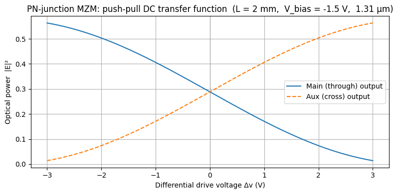
fig, ax = plt.subplots(figsize=(8, 4))
ax.plot(v_pn_drive, p_main_pn, label="Main (through) output")
ax.plot(v_pn_drive, p_aux_pn, "--", label="Aux (cross) output")
ax.axvline(0, color="gray", lw=0.8, ls=":")
ax.set_xlabel("Differential drive voltage Δv (V)")
ax.set_ylabel("Optical power |E|²")
ax.set_title(
f"PN-junction MZM: push-pull DC transfer function "
f"(L = {L_PN / 1e3:.0f} mm, V_bias = {V_BIAS_PN:+g} V, {WL_PN_UM:.2f} µm)"
)
ax.legend()
ax.grid(True)
plt.tight_layout()
plt.show()
PN-junction push-pull MZM compiled.
  Arm length        : 2.0 mm
  Series resistance : 20 Ω  (ρ_s = 0.01 Ω·µm)
  Cj0 per arm       : 0.59 pF  (ρ_C = 0.296 fF/µm)
  VπL(-1.5 V)    : 1.50 V·cm  →  Vπ ≈ 7.5 V
DC push-pull sweep (401 points): 5.313s
# ── AC small-signal bandwidth analysis ───────────────────────────────────────
# Build a minimal single-arm circuit: series resistor → PN junction → GND.
# Optical ports are terminated with a zero-power source (o1) and a 1 Ω load (o2).
#
# Key: the DC operating point (y_dc) is patched manually to V_BIAS_PN at the
# anode node.  This causes setup_ac_sweep to evaluate the Jacobians
#   G = ∂I/∂V  and  C = ∂Q/∂V
# at the correct junction voltage, giving the right Cj(V_bias) without
# requiring a VoltageSource in the AC circuit (which would short-circuit the
# RF port and prevent measurement of S21).
#
# Two-port setup:
#   Port 1 (RS,p1): RF input node — driven through the series resistance
#   Port 2 (RS,p2 = PS,anode): junction voltage node — high-Z probe
#
# The Z0=50 Ω port terminations form a resistive divider with RS, so the
# Thevenin resistance seen by Cj is R_th = (RS + Z0) ‖ Z0, not RS alone.
# S21 is normalised to its low-frequency passband value, giving a roll-off
# that starts at 0 dB with a −3 dB corner at 1/(2π R_th Cj).

pn_ac_net = {
    "instances": {
        "GND": {"component": "ground"},
        "PS": {"component": "pn_ps", "settings": _pn_inst_settings},
        "RS": {"component": "resistor", "settings": {"R": R_SERIES_PN}},
        # 1 PΩ high-Z references so Port 1 and Port 2 have a DC path to GND
        "R_ref": {"component": "resistor", "settings": {"R": 1e15}},
        "R_probe": {"component": "resistor", "settings": {"R": 1e15}},
        # Optical terminations (zero-power source + matched resistive load)
        "Src": {"component": "source", "settings": {"power": 0.0}},
        "Ropt": {"component": "resistor", "settings": {"R": 1.0}},
    },
    "connections": {
        "GND,p1": ("PS,cathode", "R_ref,p2", "R_probe,p2", "Src,p2", "Ropt,p2"),
        "RS,p1": "R_ref,p1",  # Port 1: RF input node
        "RS,p2": "PS,anode",  # Port 2: junction voltage node
        "R_probe,p1": "PS,anode",
        "Src,p1": "PS,o1",
        "PS,o2": "Ropt,p1",
    },
}

_ac_models = {k: v for k, v in _pn_models_map.items() if k != "voltage_source"}
pn_ac_circuit = compile_circuit(pn_ac_net, _ac_models, is_complex=True)

port1_node = pn_ac_circuit.port_map["RS,p1"]  # RF input
port2_node = pn_ac_circuit.port_map["RS,p2"]  # junction anode (= PS,anode)
anode_node = pn_ac_circuit.port_map["PS,anode"]

# AC sweep with Z0 = 50 Ω; y_dc provides the linearisation point
run_ac_pn = setup_ac_sweep(
    pn_ac_circuit.groups,
    pn_ac_circuit.sys_size,
    [port1_node, port2_node],
    z0=Z0_RF,
)
freqs_ac = jnp.logspace(7, 11, 300)  # 10 MHz – 100 GHz

# ── Physical helpers ──────────────────────────────────────────────────────────
Cj0_arm_F = CJ0_PER_UM_FF * L_PN * 1e-15


def Cj_depletion(v, Cj0=Cj0_arm_F, Vbi=1.79, M=0.49):
    """Abrupt-junction depletion capacitance at reverse bias v (V < 0)."""
    ratio = float(v) / Vbi
    return Cj0 / (1.0 - ratio) ** M


def R_thevenin(r_series, z0=Z0_RF):
    """Thevenin resistance seen by Cj with Z0 terminations at both ports.

    R_th = (R_series + Z0) ‖ Z0 = Z0*(R_series+Z0) / (R_series+2*Z0)
    The normalised |S21| −3 dB corner occurs at f = 1/(2π R_th Cj).
    """
    return z0 * (r_series + z0) / (r_series + 2.0 * z0)


# Helper: patch anode node to a given bias voltage
y_dc_base = pn_ac_circuit()


def y_dc_at(v_anode: float):
    return y_dc_base.at[anode_node].set(v_anode)


# ── Sweep 1: S21 vs frequency at 5 reverse-bias voltages ─────────────────────
print("--- AC sweep vs reverse-bias voltage ---")
v_biases_ac = [-0.5, -1.0, -1.5, -2.0, -2.5]
y_dc_arr = jnp.stack([y_dc_at(v) for v in v_biases_ac])

start = time.time()
S_bias_all = jax.jit(jax.vmap(lambda y: run_ac_pn(y, freqs_ac)))(y_dc_arr)
S_bias_all.block_until_ready()
print(
    f"  {len(v_biases_ac)} bias pts × {len(freqs_ac)} freqs: {time.time() - start:.3f}s"
)

# ── Sweep 2: S21 vs frequency at 5 series-resistance values ──────────────────
print("--- AC sweep vs series resistance ---")
r_vals_ohm = [5.0, 10.0, 20.0, 35.0, 50.0]  # all give f_3dB > 10 GHz at L = 2 mm
y_dc_vbias = y_dc_at(V_BIAS_PN)
S_rvals_list = []
for r in r_vals_ohm:
    g = update_params_dict(pn_ac_circuit.groups, "resistor", "RS", "R", r)
    circ_r = pn_ac_circuit.with_groups(g)
    run_r = setup_ac_sweep(
        circ_r.groups, circ_r.sys_size, [port1_node, port2_node], z0=Z0_RF
    )
    S_rvals_list.append(jax.jit(run_r)(y_dc_vbias, freqs_ac))
print(f"  Done ({len(r_vals_ohm)} resistance values)")

# ── Plot ──────────────────────────────────────────────────────────────────────
# |S21| is normalised to its passband (low-frequency) value so the roll-off
# starts at 0 dB and the −3 dB corner is at f = 1/(2π R_th Cj).
freqs_GHz = np.asarray(freqs_ac) / 1e9
fig, (ax_b, ax_r) = plt.subplots(1, 2, figsize=(13, 5))

# Left: bias sweep (fixed RS, varying V_bias)
S21_bias = np.abs(np.asarray(S_bias_all[:, :, 1, 0]))  # (n_bias, n_freq)
cmap_b = plt.cm.plasma(np.linspace(0.15, 0.85, len(v_biases_ac)))
for i, v in enumerate(v_biases_ac):
    Cj = Cj_depletion(v)
    f3dB = 1.0 / (2.0 * np.pi * R_thevenin(R_SERIES_PN) * Cj)
    S21_norm = S21_bias[i] / S21_bias[i, 0]  # normalise to passband = 0 dB
    ax_b.semilogx(
        freqs_GHz,
        20.0 * np.log10(S21_norm + 1e-12),
        color=cmap_b[i],
        label=f"V = {v:+.1f} V  →  f₃dB ≈ {f3dB / 1e9:.1f} GHz",
    )
ax_b.axhline(-3, color="gray", ls="--", lw=1.0, label="−3 dB")
ax_b.set_xlabel("Frequency (GHz)")
ax_b.set_ylabel("|S₂₁| normalised (dB)")
ax_b.set_title(f"Bias sweep  (Rₛ = {R_SERIES_PN:.0f} Ω, L = {L_PN / 1e3:.0f} mm)")
ax_b.legend(fontsize=8)
ax_b.grid(True, which="both", alpha=0.4)
ax_b.set_xlim(freqs_GHz[0], freqs_GHz[-1])
ax_b.set_ylim(-20, 2)

# Right: R_series sweep (fixed V_bias, varying RS)
cmap_r = plt.cm.viridis(np.linspace(0.1, 0.9, len(r_vals_ohm)))
for i, (r, S_r) in enumerate(zip(r_vals_ohm, S_rvals_list)):
    Cj = Cj_depletion(V_BIAS_PN)
    f3dB = 1.0 / (2.0 * np.pi * R_thevenin(r) * Cj)
    S21_r = np.abs(np.asarray(S_r[:, 1, 0]))
    S21_r_norm = S21_r / S21_r[0]
    ax_r.semilogx(
        freqs_GHz,
        20.0 * np.log10(S21_r_norm + 1e-12),
        color=cmap_r[i],
        label=f"Rₛ = {r:.0f} Ω  →  f₃dB ≈ {f3dB / 1e9:.1f} GHz",
    )
ax_r.axhline(-3, color="gray", ls="--", lw=1.0, label="−3 dB")
ax_r.set_xlabel("Frequency (GHz)")
ax_r.set_ylabel("|S₂₁| normalised (dB)")
ax_r.set_title(
    f"Resistance sweep  (V_bias = {V_BIAS_PN:+g} V, L = {L_PN / 1e3:.0f} mm)"
)
ax_r.legend(fontsize=8)
ax_r.grid(True, which="both", alpha=0.4)
ax_r.set_xlim(freqs_GHz[0], freqs_GHz[-1])
ax_r.set_ylim(-20, 2)

plt.suptitle(
    f"PN-junction AC bandwidth  —  Z₀ = {Z0_RF:.0f} Ω,  "
    f"Cj0 = {Cj0_arm_F * 1e12:.2f} pF,  "
    f"f₃dB at R_th = (Rₛ+Z₀)‖Z₀"
)
plt.tight_layout()
plt.show()
--- AC sweep vs reverse-bias voltage ---
/home/runner/work/simulation-templates/simulation-templates/.venv/lib/python3.12/site-packages/jax/_src/ops/scatter.py:108: FutureWarning: scatter inputs have incompatible types: cannot safely cast value from dtype=complex128 to dtype=float64 with jax_numpy_dtype_promotion='standard'. In future JAX releases this will result in an error.
  warnings.warn(
/home/runner/work/simulation-templates/simulation-templates/.venv/lib/python3.12/site-packages/jax/_src/ops/scatter.py:153: ComplexWarning: Casting complex values to real discards the imaginary part
  return lax._convert_element_type(out, dtype, weak_type)
  5 bias pts × 300 freqs: 1.321s
--- AC sweep vs series resistance ---
Done (5 resistance values)